jquery slideshow by WOWSlider.com v8.7


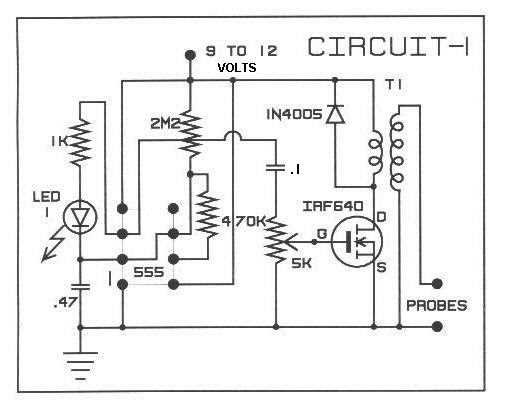
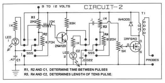
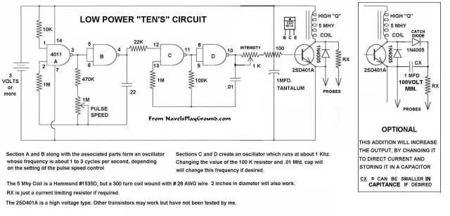
A Few Relatively Simple TENS Circuitsby navelchecker@moomia.comI initially designed these circuits for a friend who had muscle problems and while he says they did work well for him, I "DO NOT" RECOMMEND THE USE OF THEM BY ANYONE AND WITH THIS I WAVE ANY AND ALL LIABILITY FROM THERE ASSEMBLY OR USE IN ANYWAY. These circuit are to be used at your own risk And I do not imply any medical benefit can be obtained from their use. GET A DOCTORS ADVICE, BEFORE CONSIDERING USING THEM! "T1" in "A & B" circuits is a small audio transformer with the 8 ohm impedance winding connected to the Fet and the larger winding connected to the probe and ground. Turns ratio of the transformer determines voltage output. A small 6 or 12 volt power transformer can also be used. A transistor such as a 2N3055 can be substituted for the "FET" that is used in "A & B" circuits. The Base connects to the Gate, the Collector to the Drain, and the Emitter to the Source. This will result in a lower power output, but it still works. Circuit "C" is a very low powered, low voltage version, using a choke. No transformer. It will light up an NE-2 bulb connected to the output. For Informational purposes only. Low powered versions of this type of device are used by some Accupuncturists and instead of pads, the signal is applied to the needles, giving a very localized effect. Various timing capacitors and resistors can be changed for different effects. "A" This circuit is basic, producing a single pulse "B" This circuit produces an intermittent sustained pulse "C" This Low Voltage C-mos circuit produces an intermittent sustained pulse
|
 Articles and Info
 Books
Books Contact Us
 Humor Pages
 Links
Links Stories
 Training
 Welcome Page